
How to install the 3-leaf telescopic partition wall
The leaves slide together: when you open one leaf, the others follow it, linked by a belt and connectors. These are the steps of the FIP sheet for the 3-leaf partition, valid for opening to the right or to the left.
- 3 leaves that slide together
- 45 mm leaf thickness
- 16 mm overlap between the leaves
The partition and the track
The system is not compatible with pocket door frames.
The measurements
The partition is made to measure for your opening. How to measure it and which size to choose on the product page is explained in the measuring guide for the 3-leaf partition.
How to take measurementsThe track
The track is 150 mm wide and must be installed on steel or reinforced concrete beams with sufficient strength.
Three phases, 12 steps
The steps apply to opening to the right and to the left.
You'll need
- Spirit level
- 2 and 3 mm Allen keys
- Screwdriver
- Scissors
- Plumb line
- Drill
- Spanner
These are the tools listed on the installation sheet.
The track
Before inserting the carriages, the track is cleaned and the accessories are fitted.
- 1
Clean the track Caution
Before inserting the carriages, clean the whole inside of the track thoroughly.
- 2
Insert the accessories into the track
Insert the catch M into the groove of the track, minding its orientation: the end of the screw must not protrude above the top. Before fitting the guides, slide the soft-close clips into position in the direction shown on the sheet; then fit the guides and the belt fixing plate B.
The leaves
Start with door A, then connect the others one at a time.
- 3
Fix the bracket mounting piece
Fix the bracket mounting piece on the door, paying attention to the direction of the door and to the distance from both sides.
- 4
Fit the guide G under door A
When you install door A, first fit the guide G at the bottom of the door. Adjust the guide and tighten the screws: the fixing screw faces outwards.
- 5
Fit the brackets and lock the screw
After fitting the bracket, tighten the M4 × 8 Allen locking screw: it goes on every door. The height of the door is adjusted with the screws on both sides of the bracket.
- 6
Connect the belt Caution
Cut the belt to the right length and fit it in the belt connector F, with two teeth on both sides; the belt clamping is adjusted with the M4 × 30 self-tapping screw. With the door closed, the floor guide must not protrude beyond the outer face of the door.
- 7
Install door B
When you install door B, first fit the guide G at the bottom of door B. Then align door A and door B and fix the belt connector F on door B with the M5 × 12 screws.
- 8
Fix the belt in holder B
After fitting connector F, insert the belt into holder B and fix it with the door closed.
- 9
Install door C
Align doors A, B and C and fix the belt connector F of door B on door C.
- 10
Fix the belt holder O
Insert the belt of door B into the belt holder O of door A so that doors A, B and C are flush, then fix holder O.
The part letters are those on the installation sheet.
The adjustment
Stops and safety devices are adjusted on site, with the partition installed.
- 11
Adjust the buckle L and the catch M
On site, adjust the positioning buckle L and the retaining catch M to the actual measurements.
- 12
Maintenance
If the partition is used often, have it inspected and serviced regularly by maintenance staff.
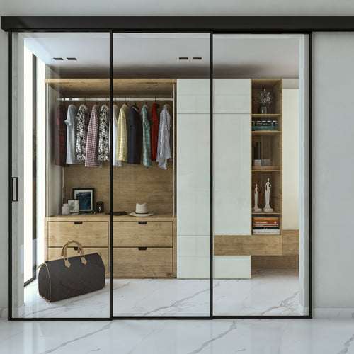
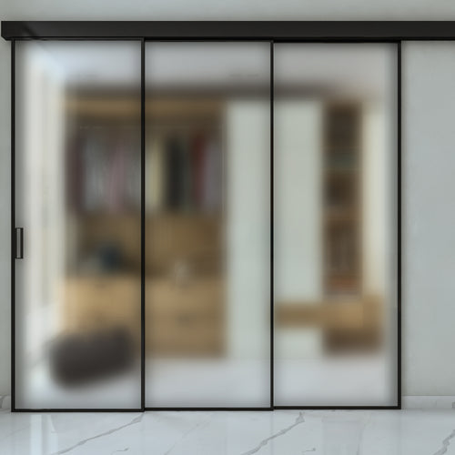
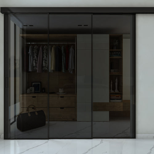
Our 3-leaf telescopic partition walls
Message us while you install the partition
Send us a photo on WhatsApp of the point where you stopped: we'll tell you how to carry on. You'll find all our other installation instructions under Technical support.


